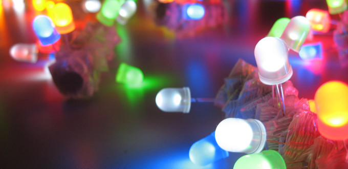
The first part of this guide talked a little about the project and gave a bit of an introduction to LEDs. This part discusses the use of LED’s in more detail with a little simple maths which can be used to determine how to power your latest LED creation.
The first thing you should know about LED’s is that they aren’t like regular incandescent light bulbs. Unlike the humble light bulb of yester-year it matters which way round you put an LED into a circuit because rather than emitting light because it gets very hot an LED emits light because of witchcraft a complex phenomenon shown by some semi-conductors. The details aren’t terribly important you just have to remember that you have to wire it up with the correct polarity.
Identifying the polarity of a new LED is generally pretty simple as one leg will be longer than the other. The long leg is the anode (positive, +ve, +, a) the short leg the cathode (negative, -ve, -, k). Additionally you may find that on the regular round LEDs there is a slight flat spot on the cathode side of the case / lense – be warned though that batch I built my cube from occasionally had a flat on the anode side so this is less than completely reliable.
You should have a data sheet or some other information about the power requirements of your LED but if not you can usually have a fairly good guess at safe parameters. The two pieces of information you really need are the forward voltage and the maximum working current. For red you’re normally looking at about 2.0v, with green about 2.5v and for blue it’s normally around 3.3v with all of them taking 20mA. These are fairly safe figures but you may come across some that are wildly different. A word of caution, you aren’t likely to ever come across a simple LED that runs on more than 4v – the physics just doesn’t work that way. If you think you have an LED that runs on more than 4v check that you aren’t reading the reverse voltage instead or that you have an LED with a built in resistor.
Reverse voltage, what’s that? Good question, it’s the voltage that the LED can handle before current is forced the wrong way through the diode. As with most things in life forcing something is a bad thing and you’ll probably find your LED no longer works afterwards.
Use a Resistor!
As a general rule LED’s should always be run with a current limiting resistor in series with them. Failure to include a resistor in the circuit will almost always result in the LED losing it’s magic blue smoke and never working again. This is because an LED doesn’t behave like a regular resistive load in a circuit which makes it very prone to burning out if the supply voltage is even slightly too high.
With an element such as a resistor, as the voltage goes up the current through the circuit goes up linearly. This effect is captured in Ohms law:
I=V/R
An LED doesn’t obey Ohms law though. At low voltages no current will flow then, at a threshold voltage, a lot of current will begin to flow. Due to imperfections in the diode and a dash more complex physics the current does rise with voltage but it’s much faster than the linear response of a resistor. What that means in the real world is that if your power supply is slightly over the voltage the LED is designed for (maybe 0.1 or 0.2v) your LED could be drawing double or more the current it was designed for.
Lets, for example, say that you have a 3.5V 20mA LED like the ones required for this project and a 5V supply. What resistor should you put in the circuit? Use Ohms law to calculate the resistor that will dissipate the excess power:
R = (Vs - Vf)/I

Where:
Vs = Supply Voltage
Vf = LED Forward Voltage
I = LED Current.

R = (5 - 3.5)/0.02
R = 75Ω
Since we have used the maximum forward voltage and current for this resistor as our inputs this is the lowest value resistor that should be chosen for this LED. Ideally you want a resistor that is slightly higher than this as a slight reduction in current generally doesn’t result in a large drop in light output, for example, there is a standard 81 ohm resistor that could be used.
Since your resistor is dissipating the excess power you need to be sure that it can cope with it. To calculate the power output of the resistor (as heat) use the power equation like this:
P = VI
P = 1.5*0.02
P = 0.02W or 20mW
Many small resistors are capable of dissipating 250mW so you shouldn’t have any trouble finding a suitable part. It’s worth noting that it won’t be exactly 20mW if you are using the 81 ohm resistor. To calculate what it would actually be rearrange Ohms law to calculate the real voltage that will be dissipated by the resistor like this:
V = IR
V = 0.02 * 81
V = 1.62

P = 1.62 * 0.02
P = 32.4mW

Or alternatively since we know I and R

P = I^2 * R
P = 0.02 * 0.02 * 81
P = 32.4mW
Notice that by picking a slightly higher resistance resistor the power dissipated by it has gone up quite significantly. This wouldn’t be a problem for a single LED since the resistor is likely to be able to cope with 250mW but for long parallel strings of LEDs this could be a serious issue.
References
- http://tinkerlog.com/2009/04/05/driving-an-led-with-or-without-a-resistor/ – Driving LEDs with and without resistors.
