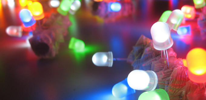
Recently, despite having dozens of other interests and things to do, I’ve been finding myself getting into electronics. I don’t suppose this will become an all consuming passion but I’d like to get to the point where I can build and analyze a simple circuit. Ever since I was at school (which was a long time ago) I’ve been fascinated by LEDs and I’d really like to incorporate light into some of my woodworking projects. With that in mind I decided to build a simple LED cube as described in this Instructable.
You might wonder why I’m bothering to write up this build when there is already a set of instructions available. There are two reasons, I’d like to provide more background information (and more detail in general) and I’d like to cover the case building in more detail. Before we go any further I want to put in a caveat: I have no formal electronics training, most of what I know I picked up in Physics A level which was about 20 years ago. Electronics runs in the family though so this isn’t completely alien to me and I have people to ask when I don’t understand something. Although we are working with low voltages here remember: if you aren’t sure don’t touch it as an electric shock can kill you instantly.
Most LED cubes that you see built have individually addressable LEDs which allows for complex animations. Most home made cubes range in size from four to eight LEDs per axis. This doesn’t sound like a lot but eight LEDs per axis means a total of 512 LEDs need to be soldered up and addressed so it’s a significant undertaking. This video shows are really nice eight-cube. The biggest cube that I’ve found is 32 LEDs per axis and can be seen here at 32,768 components I can only assume it was built by a team or perhaps by machine.
As this is a “my first electronics project” we’ll keep it simple and build a cube with random animations / colour changes. This can most easily be achieved by using LED’s that come complete with a tiny timer circuit built in like these (sorry if the link goes dead). The timer circuit makes the LED colour change in a fixed pattern but since no two timer circuits are exactly the same if you power up two LEDs at the same time you’ll notice that they go out of sync with one another. In fact the timers in the LED’s recommended here are terrible and the LEDs go out of sync almost immediately, I have a set of Christmas lights that work on the same principal that take a couple of minutes to properly go out of sync.
A regular multi-colour led will typically have three LED’s and three or more legs. The higher leg count is needed to supply power to the different LED chips that in the single casing. A fully tunable LED, one that can display any colour, will have four legs powering separate red, green and blue LEDs. The LED’s we will be making this cube from only require two legs as the built in timer handles supplying power to the separate light emitting chips.
References
- http://led.linear1.org/1led.wiz – LED resistor calculator.
- http://www.kpsec.freeuk.com/components/led.htm – LED and electronics information.
- http://www.hobby-hour.com/electronics/resistorcalculator.php – Resistor calculator.
