Fitting the motor posed some interesting problems since I had completely neglected to design in any way of getting to the feet to insert bolts. Fitting a carriage to the motor which could be more easily attached was clearly out as I had only a few millimetres of clearance above the motor so it was time to get inventive.
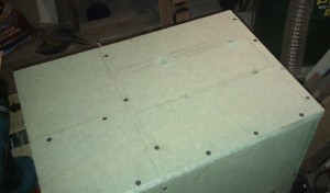
First things first though, the motor had to be able to slide sideways to tension the belt so I marked up the base of the case and drilled some holes then used the jigsaw to cut tracks between them. I then repeated the process when I noticed I hadn’t cut them long enough, sigh.
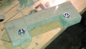
One thing I really didn’t want was dirty great lengths of bolt sticking out the bottom of the case. Ideally I wanted the case to sit flat on the base but I had resigned myself to fitting feet in order to bolt the motor down. What that meant in principal was that I needed the bolt head on the bottom and the nut inside the case. This is rather easier said than done though. The back two mounting holes for the motor feet could probably just about be accessed by a spanner but there was no way I was going to be able to get to the front two feet which were buried deep inside the case. I could cut a hole in the case but that felt very defeatist. Instead I came up with these mounting plates with embedded nuts.
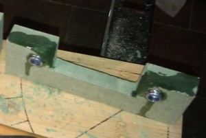
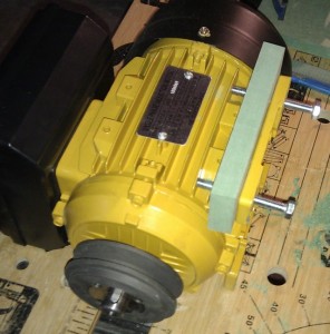
They are designed to sit over the top of the motor feet and press down onto the motor once the bolts are done up. They required a little shaping to fit the motor which was done with a rough rasp. Unfortunately the nut holes are rather close to the edge and as I sunk them in the middle of the MDF started to spread. I’m pretty sure it would have held on it’s own but I dribbled a tube of CA glue over the exposed areas just to make sure.
This picture shows the motor being tested fitted with one of the clamps.
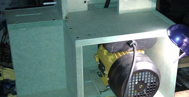
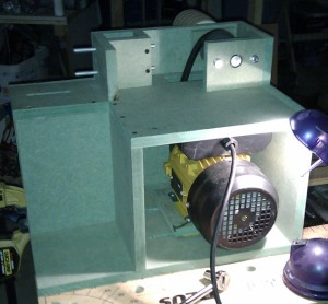
And finally here is the motor with both the clamps in place. I haven’t tensioned the belt yet in this photo as it was easier to get a shot with the motor shoved to one side.
