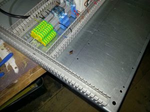
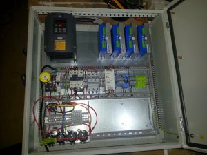
With the basic circuit checked and holes drilled for everything that would mount to the panel it was time to get the panel into the case.
Now getting the panel into the case sounds like it should be fairly easy task but take it from me it’s not. Well it’s not unless you enjoy visiting A&E because you’ve cut one of your fingers off. The mounting panel on it’s own doesn’t weight all the much, a couple of kilograms probably, but it’s got no hand holds, sits flush with the back of the case and is awkward to get to because of the case sides. Right from the word go when I first took it out the case I knew it was going to be a pain to get back in fully loaded.
The real problem was the power supply, the coil weighs in at 7 kilos and is up one corner which makes the panel badly balanced. The sharp edges on the bottom of the mounting panel also made me seriously hesitant to be putting my fingers under the panel as I lifted it into the case. In the end I came up with what I think is in ingenious solution.
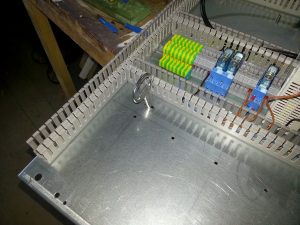
What I needed was some way to lift the panel from above. I tried using the DIN rail but I couldn’t get a good grip on it and the power supply was causing the panel to tip. I figured that the power supply housing was more than strong enough to lift the whole panel and it was easy enough to get a grip on so that would do for one hand hold. What I needed though was something up the top right near the drivers. For a second I considered just holding on to one of the steppers until common sense kicked in again. My thinking turned to expanding clips that would go through a hole and could be released from above once the panel was in.
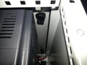
I don’t know what made me think of it but I remembered the key to the cabinet was both sturdy and perfectly designed to lock into place but be removable from above. As luck would have it the wings on the key were about the same height as the return on the mounting panel as well. I quickly drilled a hole and set about filing an appropriate keyhole. I re-mounted all the parts on the panel and lifted it into place. It was at this moment I got my biggest piece of luck to date.
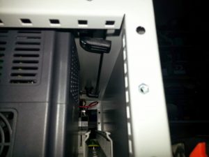
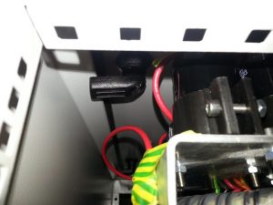
Despite all my planning I’d completely forgotten to take into account the catches holding the door closed. I’d gone out of my way to make sure I didn’t hit any studs on the inside of the door and been blind to the catches. I realised my mistake as soon as I put the panel in and I really didn’t want to have to lift it out again. Anyway, I carefully closed the door and stuck my phone up inside the case to see what the situation was as it was almost impossible to see in. Imagine my relief when saw these photos, it looks like I planned it.
As the panel was in and the door was closing I decided to fit the door mounting switch. This is a fiddly looking two part contraption, the switch part attaches to the DIN rail and the handle attaches to the door. There’s a dodgy looking plastic interconnection part that then links one to the other. The first step is to determine where on the door the switch should be placed.
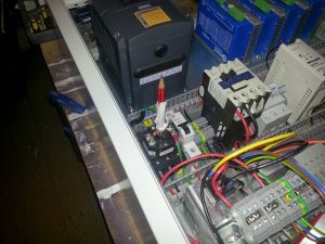
The instruction sheet, of course, gives no hints as to how you are supposed to find the correct location for the handle on the door. Taking the handle to pieces and examining it lead me to the conclusion that while there was a lot of adjustability vertically (from the switch to the door) there was almost none in the plane of the mounting panel. This seems strange as the DIN rail is almost certainly going to have been mounted before the door switch so the switch should follow the DIN’s lead not the other way around. Anyway, what that meant was I had to find, with some reasonable accuracy, where on the door the switch would mount. After a little head scratching I stuck a pencil in the switch. This isn’t any old pencil though, this is a pencil that is just the right length so that it sticks slightly above the lip of the cabinet and touches the back of the door, I also wrapped it in paper so that it was a good tight fit in the switch.
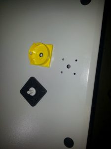
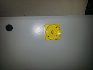
Once I had a mark on the back of the door it was just a matter of drilling the various holes. Drill the centre hole first slightly larger than you need then mount the yellow plate. This will allow you to correct for any slight misalignment. Now mark up for the four mounting holes and dill them. The switch is attached to the door using M4 counter sunk bolts (not supplied) which screw straight into the backing plate, no nuts required. I have to say I think it’s incredibly stingy not to have supplied the four bolts needed. What do they think people are going to do with the switch without the bolts? The last step is to cut the connection rod down to size. There’s really no easy way to measure this and it’s mostly a case of trial and error, I got away with making just two cuts. There’s probably a good 10mm of adjustability in the connecting rod though so you don’t have to be very accurate.
A word of warning, make sure you cut the correct end of the connecting rod off! One end has a threaded hole needed for the handle connector, this is the end you want to keep. It’s very tempting to just place the full length connecting rod in the switch and mark where you want to cut using the case as a reference. This will almost certainly result in the rod being cut to the wrong length. A better approach is to unscrew the plastic connector from the top of the rog and put it into the switch upside down. Now when you mark the rod you’ll cut off the correct end.
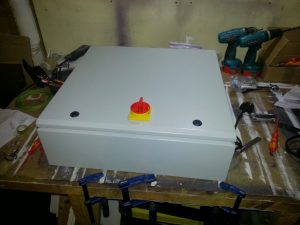
To wrap up this article here’s a gratuitous shot of the control case so far.

