Finally, the power supply is finished and I’m pleased to say that never in the history of powering up a transformer has there been so little to get excited about.
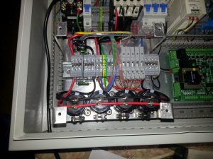
First off a quick picture of “bad” power supply, for old times sake. Bye bye breaker tripper, you won’t be missed.
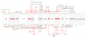
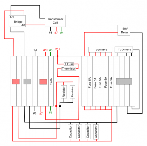
So, back in part nine I discussed the new design for the power supply. As I said back then I thought there might be some problems with the timer relay not fitting in because of the capacitors. Well not only did it not fit in because of the capacitors it failed to fit under the protective cover which was something I hadn’t considered. The only solution was to put the timer relay onto the main DIN rail which was an option I’d considered but wasn’t as keen on because it means the power supply is no longer modular. It turned out I had no real choice though so everything on the DIN rail moved up a few millimetres which of course meant moving all the cables to new slots. The upside of moving the timer to the main rail was a bit more space on the power supply rail to mount additional connectors as it was starting to look crowded. The new wiring diagram looks like this, both the main rail as well and the power supply diagrams are now needed.
The first problem I had was splitting the power from the 6A breaker. The initial design had everything splitting at DIN blocks but space constraints meant that this was no longer possible (actually, it turned out I might have been able to fit a couple of DIN blocks in between the 6A breaker and the timer – it didn’t look like it at the time). The 230V AC coming from the breaker had to be split with one path going to the inrush circuit and the other going to the timer. The path to the timer had to be further split with one side forming the relay controlled supply and the other powering the timer circuit itself.
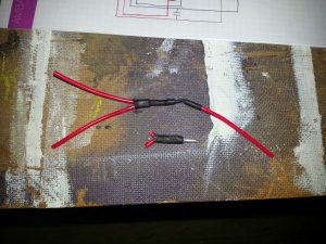
When I wired up the test stepper I noticed that two 1mm wires with thin sheath fit very neatly into a 2.5mm bootlace ferrule so I decided to repeat that here but there was a bit of a problem. The stepper control cable is shielded and the inner cables have thin sheath, the cable I’m using for the main cabinet is tri-rated and has quite a thick sheath. I explored the option of soldering two ends together to create a Y but in the end I settled on splitting the plastic portion of the ferrule and then encasing the end in heat shrink. The example below is my first attempt, the couple of two-to-one bootlaces in the case are much tidier and I’m more than happy they are safe.
With that problem solved I turned my attention to the small circuit board I needed to make to hold the inrush circuit and bleed resistors. I redid the calculations for the bleed circuit and rather than have all four resistors I went with just two. This gives me a dissipated power of 1.1W across the two resistors which are rated at 3W each so nearly a six fold safety margin. The total current is also a tiny 15mA so the circuit board can easily handle it. Calculation shows that this bleed resistance will take the capacitors from 75V to 1V in about 15 minutes. While this is quite a long time to wait I figured that most of the time I’ll have steppers attached to the supply so the drain will actually take just a few seconds.
I’ll admit up front that I don’t know a huge amount about electronics but one thing I do know is you don’t want arcing between components in your system so it’s a good idea to keep high voltage bits (that are at different potentials) away from each other. The recommended separation between live and neutral traces at 240V is 3.2mm according to this post which means removing at least two rows of holes on the board. The hole pitch is 2.54mm so two holes should give me at least 5mm of separation. I read that a good way of removing traces on strip-board was to lay a bead of solder on the trace then turn up the iron, melt the glue and peel off the trace. I tried this with the perf board I was using but the results were less than impressive. Mostly I ended up burning the glue (which absolutely stank) and the end result was a mess anyway.
The solution I came up with was to drill out the holes to remove the inner section and then countersink to remove the edge.
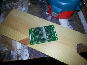
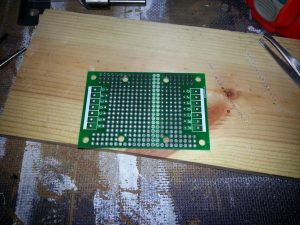
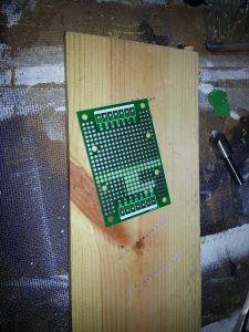
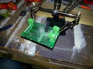
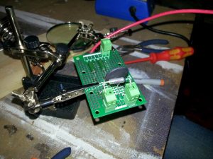
The first image shows a row of holes after they have been drilled out. A regular drill driver with a 1mm bit is all that is required. The second picture shows the AC/DC circuit separation after cleaning up with a countersink and the third image shows some additional isolation for the end of the inrush circuit. Note in the final image I also had a shot at removing the F and G holes but I didn’t bother removing the tracks as the separation was already great enough. To be fair I think just removing the two rows across the middle would have been enough. The inrush circuit doesn’t have a neutral line and the difference in potential between components is tiny (the thermistor is only 10 Ohms and that is the biggest drop by far).
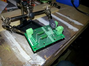
While I had planned everything out to the nth-degree on paper nothing beats actually placing the components on the board to make sure everything will fit. In my plan I seemed to have more space for the bleed resistors so perhaps I drew them a little small. I didn’t want to bend the legs any closer to the resistor body though so that is the layout I’ll go for.
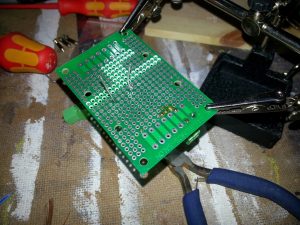
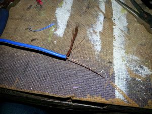
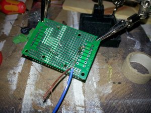
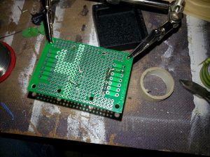
The first picture shows the bottom two legs of the bleed resistors soldered into place and snipped off short. I tried do the join-the-dots trick with the solder to make a trace on the board but the solder kept running through the holes. After a few failed attempts I settled on the alternative approach of running a small bit of copper wire along the dots. I stripped a short length of cable and twisted together a few strands as shown in the second picture. The third picture shows the wire partially soldered into place and the final picture shows it cut off. It’s not the neatest job in the world but it’s more than enough to carry the 15mA that will be flowing along it.
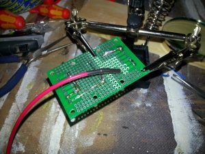
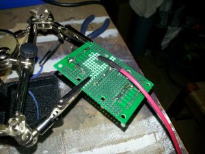
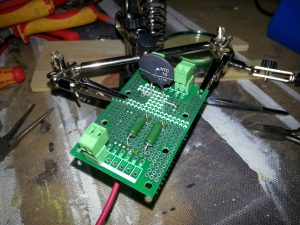
Having had some success I turned my attention to the rest of the board and promptly forgot to take any photos. The first two photographs above shows the completed underside of the board. I used the same technique of soldering a bit of wire across the holes to increase the current carrying ability of the board (and to make a connection). Note that the wire on the soft-start side is significantly thicker than on the bleed side. The soft-start side needs to be able to handle about 5A for a couple of seconds under normal circumstances and potentially indefinitely under one failure mode (the timer relay doesn’t close and the thermal fuse doesn’t blow). To connect the thermistor to the rest of the circuit I soldered a piece of 1mm cable to the leg and double coated the join with heat shrink. I don’t particularly like this as it’s a mechanically weak point in the circuit but to provide some strain relief I slipped the cable through the mounting hole in the circuit board – it was a perfect fit. The final image shows the top side of the finished board.
Although the soldering on the board is finished I still needed to add the thermal fuse. This was a little more complicated than I wanted it to be because the fuses I bought had one long leg and one short (I think they are designed to stand upright on circuit boards.
A quick bit of wire bending soon had the fuse in place but the legs were only just long enough. I bent the thermistor towards the mounts a little and then used the fuse to push it back, this way the fuse is always in good thermal contact with the thermistor. The fuse is also placed so that it will be on the upper side of the thermistor when the cabinet is finally mounted.
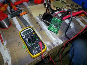
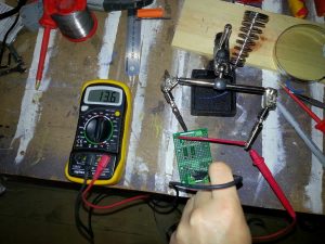
The last thing to do is check for shorts and resistances to make sure the circuit is wired as expected. The bleed resistors should be 5k Ohms since there are two 10k Ohms resistors in parallel, image one shows the meter reading 4.99k Ohms – I can live with that. The second image shows the resistance of the soft start circuit. The thermistor is designed to be 10 Ohms at 20 deg C but the error margin is huge on these devices and it was a little below 20 deg C in my workshop so the 13.6 Ohms I measured it as is probably pretty much spot on. If you look closely at the first image you will notice that I have also added some isolation to the soft start side of the circuit. I wasn’t happy with how close the two traces were at the corner considering there was an 80V potential between them. While adding this separation I discovered a 3.2mm drill bit is actually quite a bit better at removing the edge of a hole than the countersink.
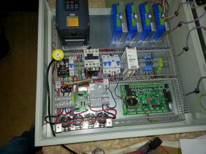
The final image shows the soft start circuit in place. There’s still some wiring to do but this article has run long already so that will be in the next part.

